Εμφάνιση αναρτήσεων με ετικέτα Radio Amateur. Εμφάνιση όλων των αναρτήσεων

Πέμπτη 2 Απριλίου 2026

QSL World


 Our tool uses AI and QRZ.com API to help you visualize your ham radio contacts. Simply upload your ADIF file (.adi file), and it will generate a clear map of your QSOs. Whether you’re new to ham radio or a seasoned operator, this tool is here to make mapping your contacts easy and accurate.

More: https://qslworld.com/

Σάββατο 5 Δεκεμβρίου 2020

HAMLOG.online - Global log and hamradio awards


HAMLOG service has been operating since 2015. The prototype was the autocount system for the RAEM-110 memorial, which made it possible to download the connections of special stations, as well as issue diplomas in electronic form.

More info: https://y7k5t6wdh4kiq7k4gcdygd2zmy--hamlog-online.translate.goog/

Τρίτη 10 Δεκεμβρίου 2019

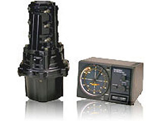
Installation Antennas to rotator (Tower-Mounted Antennas)


In the preferred tower-mounting configuration, the antenna Wind Loading Area must be less than 1 m2 (G-450A) or 2 m2 (G-650A), and the “K” factor (see below) must not exceed 100 (G-450A) or 180 (G-650A), where K = [Antenna Turning Radius (m)] x [Antenna + Mast Weight (kg)]. Refer to the antenna manufacturer’s specification sheet for determining the turning radius and weight of the antenna
  
Example: In this example, a 14 MHz 3-element Yagi of Turning Radius 7.5 m, Weight of 14 kg, and Surface area of 0.7 m2 is proposed for tower mounting below a 3-element 21/28 MHz trapped Yagi of Turning Radius 3.5 m, Weight of 13 kg, and Surface Area of 0.3 m2 . The mast weight is 5 kg.
 The antenna system K factor, then, is the sum of the two antenna K factors:
 K1 = K factor of 14 MHz 3-element Yagi.
K1 = Turning Radius (7.5 m) X Weight (14 kg + 2.5 kg) = 123.75
         |              |
Antenna Weight      Mast Weight (5 kg ÷ 2)
  K2 = K factor of 21/28 MHz 3-element trapped Yagi.
K2 = Turning Radius (3.5 m) X Weight (13 kg + 2.5 kg) = 54.25
         |              |
Antenna Weight      Mast Weight (5 kg ÷ 2)
 KTotal = K1 + K2 = 123.75 + 54.25 = 178
 The antenna system Wind Loading Area is: 0.7 m2 + 0.3 m2 = 1.0 m2|
 Note: In such “Christmas Tree” installations, compute the mast weight separately for each antenna, using the relative heights of the two antennas to apportion the mast weight.
Refer to the antenna manufacturer’s specification sheet for determining the weight and the surface area of the proposed antenna.

More: https://www.yaesu.com/indexVS.cfm?cmd=DisplayProducts&ProdCatID=104&encProdID=9CD2145C24AE53C5A6C62D7D703A9F3C&DivisionID=65&isArchived=0


Δευτέρα 2 Δεκεμβρίου 2019

Installation Antennas to rotator (Pole-Mounted Antennas)


Pole-Mounted Antennas
Mounting of the rotator on a pole or mast results in a significant de-rating of the size of the antenna which can be mounted, due to the tremendous bending forces applied to the rotator’s clamps. For pole mounting, the attached antenna must have a net mounted weight (combined weight of antenna plus mast) of 10 kg or less, and the product of multiplying the [Antenna Wind Load Area (in m2 )] by the [Height of the Antenna Mast (in m)] must be 0.25 or less.
[Antenna Weight] + [Mast Weight] ≤ 10 kg.
[Antenna Wind Load Area] X [Height of Antenna Mast] ≤ 0.25
Refer to the antenna manufacturer’s specification sheet for determining the weight and the surface area of the proposed antenna.
Yeasu Rotators:
The antenna Wind Loading Area must be less than ,=<0,25 (G-450A) & (G-650A), or =<0,45 (G-1000DXC), or =<0,80 (G-28000DXC)
Example:
For a 50 MHz 5-element antenna of surface area of 0.3 m2 , the above specifications for pole mounting will be met if (A) the antenna is mounted on a mast not longer than 0.8 m (0.3 X 0.8 = 0.24 < 0.25), and (B) if the mast weight plus the antenna weight is less than 10 kg. However, if the mast is 1 meter long, the specification will be exceeded (0.3 X 1 = 0.3 > 0.25).

More: https://www.yaesu.com/indexVS.cfm?cmd=DisplayProducts&ProdCatID=104&encProdID=9CD2145C24AE53C5A6C62D7D703A9F3C&DivisionID=65&isArchived=0

Δευτέρα 14 Οκτωβρίου 2019

Coaxial Cable Data

Type
50MHz
loss/max pwr
144MHz
loss/max pwr
432MHz
loss/max pwr
1296MHz
loss/max pwr
diameter
velocity
factor
Aircom+

4.5 / 1000
8.2 / 530
14.5 / 300
10.8
0.85
Aircell 7
4.8 / 1000
7.9 / 800
14.1 / -
26.1 / 190
7.3
0.83
Ecoflex 10
- / -
4.8 / 950
8.9 / -
16.5 / -
10.2
0.86
Ecoflex 15
1.96 / -
3.4 / 1800
6.1 / -
11.4 / -
14.6
0.86
H 100
2.8 / -
4.9 / 1000
8.8 / 530
16.0 / 130
9.8
0.84
H 155
6.5 / -
11.2 / 240
19.8 / 90
34.9 / 49
5.4
0.79
H 500
2.9 / -
- / 1000
- / 530
17.4 / 130
9.8
0.81
H 2000 flex
2.7 / -
4.8 / 1600
8.5 / -
15.7 / -
10.3
0.83
RG 55

18.5 / 300
34.0 / 200
60.0 / 100
5.4
0.66
RG 58 CU
11.0 / -
20.0 / 240
40.0 / 90
90.0 / 49
5.0
0.66
RG 174 U

34.0 / 95
60.0 / -
110.0 / 30
2.8
0.66
RG 213 U
4.3 / -
8.2 / 800
15.0 / 290
26.0 / -
10.3
0.66
RG 223 U

18.5 / 300
34.0 / 200
60.0 / 100
5.4
0.66
Cellflex 1/4"

5.5 / 1200
9.0 / 750
18.0 / 400
8.0
0.85
Cellflex 3/8"

3.8 / 2800
6.5 / 1200
13.0 / 680
15.0
0.85
Cellflex 1/2"

3.0 / 2800
5.6 / 1600
10.0 / 850
16.0
0.88
Cellflex 5/8"

2.5 / 4000
4.0 / 2300
7.2 / 1350
23.0
0.85

loss : dB per 100meters   -   max pwr : Watts   -   diameter : millimeters

Παρασκευή 23 Αυγούστου 2019

BV software for QSL Management and Label/QSL Printing

BV is a professional software for QSL Management and Label/QSL Printing - developed since 1989 by Bernd, DF3CB. It is mainly designed for the contester and QSL manager with high QSL quantities but useful for all other QSL'ing purposes as well.

More: https://www.df3cb.com/bv/

Τετάρτη 6 Φεβρουαρίου 2019

ES5TV 15m 8x5 Elements H Frame Stack

70 meters high tower carries 8 5-element 15m yagis as pairs separated horizontally by 12 meter distance and vertical stacking is 14 meters. The heights of the antenna pairs are 64, 50, 36 and 22 meters. 

Πέμπτη 29 Νοεμβρίου 2018

JTDX "JT & T modes for DXing",

JTDX means "JT & T modes for DXing", it is being developed with main focus on the sensitivity and decoding efficiency, both, in overcrowded and half empty HF band conditions. It is modified WSJT-X software forked from WSJT-X r6462.
JTDX supports JT9,
 JT65, T10 and FT8 © digital modes for HF amateur radio communication, focused on DXing and being shaped by community of DXers.
It is created with contributions from DK7UY, DO1IP, ES4RLH,G7OED, MM0HVU, RA4UDC, SV1IYF, UA3ALE, US-E-12, VE3NEA, VK3AMA,  VK6KXW, VK7YUM and LY3BG family: Vytas and Rimas Kudelis.

Παρασκευή 14 Απριλίου 2017

How to work FM satellites

Simon 2E0HTS has released a video that shows him making contacts via the amateur radio satellite SO-50.
This satellite carries an FM transponder that receives signals on 145.850 MHz and retransmits them on 436.800 MHz (+/- 9 kHz Doppler shift). Operation is a little more complex that some other satellites since the transponder needs to initially be activated by a CTCSS (PL) tone of 74.4 Hz which starts a 10 minute timer and then a 67 Hz tone is used for the contact.
Note: If your radio has selectable FM filters use the wider filter designed for 5 kHz deviation FM which is sometimes referred to as a 25 kHz channel spacing filter.

 MORE: https://amsat-uk.org/beginners/how-to-work-fm-satellites/

Τετάρτη 25 Ιανουαρίου 2017

Understanding Single Sideband (SSB)

A new Technician Class operator is likely to get started in ham radio with VHF and UHF phone operations using FM simplex channels and repeaters. The channelized world of VHF/UHF FM offers relatively simplicity of operations and is a great way to get on the air immediately upon earning the Technician Class license. However, after mastering repeaters and gaining comfort with on-air FM phone QSOs, the next step for many hams is the more challenging domain of single sideband (SSB) phone operations.

INFO: http://www.hamradioschool.com/understanding-single-sideband-ssb-2/

Σάββατο 23 Ιανουαρίου 2016

Super J-Pole Antenna for the 4m

Super J-Pole Antenna for the 70Mhz (4m) Amateur band.
The Vortex ‘Super J-Pole’ Antenna consists of a five eighth wave vertical radiator, a half wave tuning section and a half wave top section. At the base, a quarter wave matching stub forms the classic ‘J Shape’. The addition of the extra half wave top section boosts the gain over a standard J-Pole. The Super J-Pole has an added advantage that tuning can be varied over a fairly wide frequency range by moving the feed-point location up or down. This also gives the user finer control over the impedance and match. The antenna is end fed and has an omni-directional radiation pattern and requires no ground plane or radials. The antenna has a nice low angle of radiation, typically 8 degrees when mounted at 4m in height. This angle reduces further the higher the antenna is mounted. A typical installation with the antenna at 8 meters above ground sees the angle reduce to 5 degrees and the gain increases to 7.29dbi when ground reflections are added.

INFO: http://ei4dib.blogspot.ie/2015/09/vortex-super-j-pole-antenna-vhf-70mhz.html

Σάββατο 31 Οκτωβρίου 2015

ΡΑΔΙΟΕΡΑΣΙΤΕΧΝΙΚΕΣ ΚΕΡΑΙΕΣ ΚΑΙ Ε.Ε.Α.Ε.

ΡΑΔΙΟΕΡΑΣΙΤΕΧΝΙΚΕΣ ΚΕΡΑΙΕΣ ΚΑΙ Ε.Ε.Α.Ε.
του  νομικού Κωστ/νου Τρανσβαλίδη (SV2HPH)

    Είναι πιθανόν γνωστό σε αρκετούς συναδέλφους η πρόσφατη περιπέτεια της Ραδιολέσχης Καρδίτσας, εις βάρος της οποίας επιβλήθηκε τέλος («χαράτσι») από την «Ελληνική Επιτροπή Ατομικής Ενέργειας» (εφεξής Ε.Ε.Α.Ε.), ύψους 400,00 Ευρώ, το οποίο αφορούσε το ετήσιο τέλος μετρήσεων κεραιών, για το έτος 2014.
    Όπως προκύπτει από το σχετικό παραστατικό που εξέδωσε η Ε.Ε.Α.Ε. στις 23/3/2015 και επ’ονόματι της Ραδιολέσχης Καρδίτσας (στην οποία έχει αποδώσει τον Κωδικό Πελάτη 20154300),πρόκειται για το υπ’αριθμόν 83144 τιμολόγιο παροχής υπηρεσιών και διάθεσης υλικών, ως προσφερθείσα δε υπηρεσία αναγράφεται το «ετήσιο τέλος μετρήσεων κεραιών – ραδιοφωνικός σταθμός #έτος 2014». Τέλος από το ίδιο παραστατικό, προκύπτει ότι η τιμολογηθείσα συνολικά αξία ανέρχεται σε 400,00 Ευρώ και αφορά 2 κεραιοσυστήματα, με τιμή μονάδας 200,00 Ευρώ.
    Στο καταβλητέο ποσό δεν συμπεριλαμβάνεται ΦΠΑ, ούτε οιαδήποτε άλλη εισφορά, κράτηση ή εν γένει επιβάρυνση.

Τρίτη 7 Ιουλίου 2015

Big Wheel Antenna for 2m, 70cm and 6m

The “Big Wheel” is a horizontal polarized omni directional antenna. Usually highly directional antennas are used on VHF and UHF, which have the capability to bundle the radiated energy in one direction and eliminate interferences from unwanted directions. But these effects are not always welcome. With directional antennas it is nearly impossible to monitor a frequency for signals from any direction. Usually the directional antenna stays in the direction where the most signals are expected from and some rare contact in an other direction is lost. In such cases the Big Wheel is an ideal antenna which should be used together with a directional antenna.
Big Wheel antennas by WiMo are made of stainless aluminum, all other hardware is made of stainless steel. The antenna gain is approx. 3dBD, each Big Wheel has a N-jack (female). By vertical stacking of two Big Wheels you get a gain of approx. 5dBD. To connect two antennas to one coax feed a usual phasing harness can be used.

More Info: http://www.wimo.de/big-wheel-antennas_e.html